Electrical/Electronic
The electrical system comprises: Building the circuits of a drum motor, a fan, a heater, and a temperature and humidity sensor.
Requirements
Functions
- The drum motor should turn the drum.
- The fan should move fresh air into the drum.
- The heater will heat the air inside the drum.
- The temperature and humidity sensor monitors the real-time temperature and humidity of the air in the drum.
Objectives
- The efficient and safe functioning of the electrical components of the dryer.
- The user-controllable wind speed.
- Accurate temperature detection and control.
- Reversible motor.
- Accurate humidity detection.
Constraints
Power Constraints:
- Specific power limitations of 24 VAC
- Consideration of available power supply
- Ensuring electrical components and circuits stay within maximum power capacity
- Considering energy efficiency requirements
Space and Size Limitations:
- Electrical components must fit within the overall design and dimensions of the dryer
- Working within given space constraints
- Ensuring proper placement and integration of components
- Considering factors such as ventilation, heat dissipation, and maintenance access
Cost and Material Constraints:
- Working within a specified budget for electrical components
- Selecting cost-effective components and circuits
- Meeting required functionality while considering trade-offs between performance, reliability, and cost
Time Constraints:
- Facing time constraints imposed by project deadlines
- Managing tasks efficiently
- Ensuring timely design, testing, and integration completion
- Meeting the project timeline
The Design
Power Supply

To convert the 24V AC power from the source into a 9V DC output (required for powering the heater), a rectifier is used on the breadboard. The circuits incorporate various electrical components like LEDs, resistors, and capacitors. LEDs are employed to indicate the system’s operational status, allowing users to determine if the power is connected. Capacitors play a protective role by smoothing out fluctuations in the electric current. The project is limited to a maximum voltage of 24V AC. Since most components operate on DC, the engineering team uses a bridge rectifier circuit, utilizing diodes and capacitors, to convert the voltage to 9V DC. To power the Arduino Uno, which requires a ~9V DC supply, a voltage regulator and capacitors are utilized to reduce the voltage from 24V to 9V. This configuration is illustrated in Figure 1.

Fan
The fan circuit operates using a 9V DC power supply shown in Figure 2. It is connected to an Arduino for controlling the fan’s speed. The circuit consists of components such as the fan itself, a 10k resistor (R2), a 0.1uF capacitor (C5) rated for over 50V, a MOSFET (Q1), and a diode (D1) with a 1A rating and a response time of 50ns. The MOSFET is employed to facilitate control and switching of the fan based on the output from the Arduino. A diode is included to ensure proper current direction, and a capacitor is connected in parallel with the fans to ensure circuit safety.
Two methods are available for regulating the fan speed. The first method involves adjusting the speed through programming code, while the second method entails reducing the voltage and increasing resistance to limit the electrical energy supplied to the fan. After conducting various experiments, the first method was selected to avoid potential heat damage that could occur if additional resistors and transistors were added in series.
| weight | Always on | Controlled by sensor | |
|---|---|---|---|
| Simplicity | 50% | 5 | 2 |
| Low cost | 25% | 1 | 3 |
| Energy saving | 25% | 1 | 3 |
| Total | 3 | 2.5 |

The advantage of the fan controlled by users:
- Flexibility: Users can control the operation of fans according to actual needs and personal preferences. They can choose different fan speeds or run times to suit different types of laundry or drying needs. This flexibility allows the user to personalize the drying settings according to their needs.
- Energy Conservation: User-controlled fan operation provides the flexibility to adjust the dryer’s energy consumption as needed. When only a small amount of laundry needs to be dried, the user can choose a lower wind speed or a shorter run time, thereby reducing energy waste. This can help save electricity or gas consumption.
- Item Protection: Some clothing or items may be sensitive to higher wind speeds or strong wind currents. By allowing the user to control the operation of the fan, they can reduce the wind speed or select a softer air flow to protect clothing from damage or deformation.
- Customized drying process: Different clothes or items may have different drying requirements. User-controlled fan operation can help them customize the drying process according to the characteristics and needs of the items. For example, for clothes of some special materials, users can choose low wind speed and gentle drying to ensure the quality and durability of the items.
Drum Motor

The drum motor circuit operates using a 5V DC output from the Arduino. The Arduino is connected to the motor circuit to regulate the motor’s speed. A MOSFET is utilized in the circuit to control and switch the motor based on the Arduino’s output. The components of this circuit include a motor, a resistor (R3), capacitors (C6 and C10), a MOSFET (Q2), and a diode (D1). The diode is employed to safeguard the MOSFET during switch-off, while the capacitors are used to minimize voltage fluctuations in the electrical supply. In addition, the polarity (+/-) of the motor is not significant as the motor can rotate in either direction.
One-way rotation: Traditional dryers usually use a one-way rotation design, that is, they rotate in the same direction. This design is relatively simple, and the rotation during drying can provide a certain degree of agitation and drying effect. As the heating element inside the dryer heats the air and passes it through the clothes, the clothes are agitated by the rotating drum or internal mechanism to increase the contact of the clothes with the hot air, promoting evaporation and drying. Dryers with one-way rotation usually have lower cost and simpler operation, and are suitable for general household use.
Both positive and negative rotation: Some advanced dryers adopt the design of both positive and negative rotation, that is, the direction of rotation can be changed during work. This design can provide better drying effect. The function of both forward and reverse rotation allows the dryer to change the direction of rotation periodically, for example, every once in a while. This has several advantages:
- Mixing Laundry: Both reversible turns allow for better mixing of laundry and prevent laundry from knotting or clumping. When the dryer is reversed, the clothes change from one arrangement to another, effectively loosening the interweaving and tangles between the clothes, allowing hot air to pass more easily over the surface of the clothes for a more even drying result.
- Even Heat Distribution: Reverse rotation also distributes heat more evenly, allowing clothes to dry faster. By changing the direction of rotation, the dryer can better distribute the hot air to different parts of the clothes, avoiding excessive heat accumulation in a certain area, thereby improving the overall drying efficiency.
- Reduce clothing friction: both positive and negative rotation can reduce friction between clothing, reduce wrinkles and pilling. When the clothes are rotated in the same direction, the friction between the clothes will increase, which will easily lead to wrinkles and pilling. The design of both positive and negative rotation can reduce this friction and make the clothes smoother during the drying process.
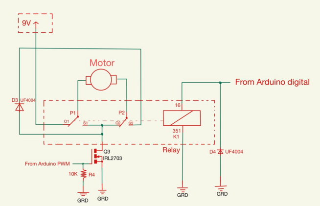
Figure 4.
Heater


The heater in this setup is powered by a 12VAC power source, which is different from the power sources of the motor and fan. The reason for using AC power is that the current flow direction does not affect the circuits’ heat generation. The components in this circuit include the heater itself, resistors, a capacitor, an LED, and a Triac. The Triac is utilized to control loads in AC circuits, precisely to control the heater using signals from the Arduino. To ensure reliable switching off of the Triac when commanded, a snubber consisting of a capacitor and resistor is included in the circuit. As the capacitor is connected to 12V AC, it is chosen with a high tolerance for peak voltage pulses for safety reasons. The Arduino is connected to the motor circuit to regulate the operating time of the heater. Additionally, a sensor is incorporated into the circuit to provide feedback to the program, enabling Arduino to control the heater’s operation based on the sensor’s return value. For a visual representation of the heater circuit, please refer to Figure 5.
| Always on | Controlled by Temperature Sensor |
|---|---|
| The heater runs at full power when the power supply is plugged in. | A circuit with a thermistor turns off the heater when the desire temperature is reached. |
The advantage of the heater controlled by temperature sensor:
- Precise temperature control: The temperature sensor can monitor the temperature inside the dryer in real time, and automatically adjust the power of the heater according to the set value. This ensures that the dryer stays at just the right temperature throughout the process, preventing items from overheating or under-warming.
- Energy Saving: Since the temperature sensor can accurately monitor and control the temperature, the dryer can automatically stop heating or reduce the heating power after reaching the set temperature. This avoids overheating and wasted energy, saving electricity or gas consumption.
- Protect the quality of items: Different items require a suitable temperature when drying, too high or too low temperature may have a negative impact on the quality of the items. By controlling the heater with a temperature sensor, it can ensure that the items are dried at an appropriate temperature, reducing damage or deformation caused by temperature changes.
- Enhanced safety: The temperature sensor can monitor the change of the internal temperature of the dryer, and trigger an alarm or automatic power-off and other safety measures when the temperature rises abnormally, so as to prevent fire or other safety accidents caused by overheating.
Temperature and Humidity Sensor

The fan circuit is powered by the power supply’s 9V DC output. To control the fan speed, connect Arduino pin to the fan circuit. MOSFETs are used to control and switch fans based on Arduino output. To assure the circuit’s safety, a diode is employed to preserve current direction, and a capacitor is linked in parallel with fans. For a visual representation of the sensor circuit, please refer to Figure 6.
Extra Feature
Multiple LED lights will be used to signal the user, for example a red light will be used to inform the dryer that the dryer has been turned on accidentally (turning on before finishing drying), and a green light will be used to inform the user that the dryer has successfully finished drying. The buzzer will be used when the user presses the button, and the dryer is off. By changing the sound frequency of the buzzer, we will play simple music when the drying is finished.

The door interlock is powered by 5V DC, connected with ground and pin, controlling the not-working of all devices when the door interlock is open.
A reversing drum is a device powered by a 9V DC source and connected to an Arduino PWM pin. It controls the operation of a motor in both counterclockwise and clockwise directions by changing the current’s direction. To ensure the safety of the circuit, regulate the circuit automatically, and switch the circuit, a relay is used.
Here’s how the components work together:
1. Reversing Drum: The reversing drum is typically a mechanical component that facilitates the change in the motor’s rotational direction. By controlling the direction of the current, it enables the motor to rotate either counterclockwise or clockwise.
2. 9V DC Power Source: The reversing drum is powered by a 9V DC power source, which supplies the necessary electrical energy for the motor’s operation.
3. Arduino PWM and Pin: The Arduino is programmed to generate PWM (Pulse Width Modulation) signals, which control the speed of the motor. By connecting the PWM pin of the Arduino to the reversing drum, the Arduino can regulate the motor’s speed and direction.
4. Relay: The relay is employed to protect the circuit’s safety and automatically regulate and switch the circuit. It acts as a switch that is controlled by a low-current signal (such as from the Arduino), while being capable of handling higher currents required by the motor. The relay can change its state (open or closed) based on the control signal received, allowing or interrupting the flow of current to the motor.
By utilizing the relay, the Arduino can control the motor’s direction by changing the direction of the current flow. This setup provides a safe and automated way to operate the motor, enabling it to rotate in both counterclockwise and clockwise directions.

Control Programs

Mechanical Design
The Mechanical sub-team should design, sketch, compare and create the mechanical components of the Dryer Machine using Solidworks, considering the following rubrics and constrains.
The two members are responsible for the design of the whole drum, the gears, the sensor mount, the heat exchanger and the lint filter.
Requirements
Functions
The Dryer Machine should have the following functions:
- Drum is able to rotate using a motor.
- Fan is able to blow hot air to the drum to dry the clothes.
- sensor mount is able to detect the temperature and humidity inside the drum.
- Heat exchanger is able to collect and transfer liquids.
- Lint filter is able to collect lint so that it will not get into the copper pipes.
- Alphanumeric LCD display and navigation buttons for user interface.
Objectives
- Low friction on the rotation.
- Less material waste.
- High heat recovery.
Constraints
- Size not exceeding 250 x 220 x 300 mm (fit within carton for copier paper).
- At least 0.5 L capacity, able to dry a cotton handkerchief, size 15 x 15 cm (± 3 cm) within 1 hour.
- Maximum allowable electrical power consumption: 24 V AC, 40 VA.
- Automatic operating mode
- Manual operating mode: able to set desired
- Drying time
- Temperature
- Dryness
The Design
The following part lists our brainstorming and the final designs for the drum, the gears, rotation system and heat exchanger system.
Drum
The designs for the drum includes front, middle, back, top and lint filter. The drum(1.35 L) is printed in 40% density so that it requires less force to rotate it.
Front |
Middle |
Back |
Top |
|---|---|---|---|
| The open of the front drum is smaller than the drum so that the clothes will not drop out. | Three impellers are added in the
drum. The reason for this is to keep the clothes spread. Without the impellers, the clothes will be rolled up which make it harder to dry completely. |
A grid is designed so that the clothes will not directly contact with the fan. It ensures the fan can working normally. Few supports are added to the back in order to increase the strength. | Tenon structure is applied in this design. The advantages of tenon includes:
|
 |
 |
  |
 |
| Front |  |
| Middle |  |
| Back |   |
| Top |  |
Lint Filter


A lint filter, also known as a lint trap, is a device or component used to capture lint and other debris that may be present in the air or water flow. Lint refers to small fibers or particles that are shed from fabrics, such as clothing, towels, or bedding, during washing or drying processes.
The functions of lint filter includes:
- Store lint
- Airflow optimization
- Protection of the fan
- Ensure perfect efficiency
In the sketch, two components joint together with one lint put in the middle. In order to collect smaller lint, we make the holes in the lint more dense(in other words, we fold it). The lint filter is printed in 40% density.
Rotation System
During the demonstration provided by professor from the first week, we noticed that the drum was just simply fixed on the support frame which produced a huge noise and friction. So after brainstorming, we conducted bearing as a replacement to make it spinning smoothly.

We also used a best of class table to rank the two designs.
| Template (fix the drum on the support) | Our Design (bearing) | |
|---|---|---|
| Simplicity | 1 | 2 |
| Nosie Generated | 2 | 1 |
| Friction Produced | 2 | 1 |
| Rank | 5 | 4 |
With less friction produced, there may be less force required to rotate the drum, which saves energy. The frame and small cylinders are printed in 90% density because it is stronger to support the drum.
Drum Drive
The two major components that can be used as drum drive are gear and belts. Despite that, a clockwork spring can also achieve the goal. It is the common item that can be seen in the measuring tape.
| Gears | Belts | Clockwork Spring | |
|---|---|---|---|
 |
 |
 |
All of the components can spin the drum so that we conducted a weighted decision matrix to help us to analyse which is better.
| Weight | Gears | Belts | Clockwork Spring | |
|---|---|---|---|---|
| Simplicity | 10% | 1 | 3 | 2 |
| Less Material Used | 10% | 1 | 3 | 2 |
| Durability | 20% | 4 | 2 | 1 |
| Higher Efficiency | 60% | 4 | 3 | 1 |
| Total | 100% | 3.4 | 2.8 | 1.2 |
The results shows that gears have longer duration and can produce higher rotating efficiency, so the gear is our final decision.
For gears, there are two types: spur gear and helical gear. To decide which is better, we lists the advantages and disadvantages for each.
 |
 | |
|---|---|---|
| Advantages |
|
|
| Disadvantages |
|
|
In the helical gear designs, there are two sizes(modules 1 and modules 2.25). We choose the gear with larger modules where the teeth are bigger. The reason for this is that larger modules seem to have larger contact space which may be more stable. The gear is printed in 25% density.
| Design 1 (modules 1) | Design 2 (modules 2.25) | Sketch |
|---|---|---|
 |
 |
 |
Heat Exchanger
The basic idea is to connect the upper part to the fan and heater. However, it is hard to remove the support in the connecting tube if we connect two parts using one tube, so we separate it into three parts. By adding the three parts together, air is able to flow from the inner drum to the fan so that the air is heated again which saves energy. The heat exchanger is printed in 25% density.
 |
 |
 |
 |
 |

As for the part two of the revised design, we dig a hole so that it is connected to the top of the heat exchanger. The reason for doing this is that the path of the air flow is too long so we aim to make it shorter.
Motor Mount
Motor Mount is used to fix the motor, avoiding it from loosing. There are basically two designs for the motor mount. In the first design, the motor is placed at the right right to the drum; In the second design, the motor is placed at the lower right to the drum. To evaluate which one matches more to our motor, we list the advantages and disadvantages for each.
 |
  | |
| Advantages | stable
easy to change size |
more space for gears
more stable |
| Disadvantages | may exceed width | hard to change size considering the angle of inclination |
Through further discussion, we think design 2 is better. By adding some extra supports, the final design looks like this (The motor mount is printed in 90% density) :

As for the gear on the motor, we use a hollow gear so that the it is lighter. In that case, smaller force can be applied to rotate it so that larger force can be used to rotate the drum rapidly. This also saves materials.
 |
 |
Sensor Mount
The sensor have two functions: detect humidity and temperature. In order to connect wires without affecting its functions, we design a mount looks like this. The sensor will attach to the back drum. A horizontal board will be placed on the embossment to fix the sensor. The final template is also shown below. There are basically two designs for the sensor mount. However, the first design is a bad design because it is hard to print and connect wires, so we choose Design 2 as the final design.
 |
 |
 |
Mechanical sub-system performance results
- The drum is rotating at a speed of 225 PWM.
- By shorten the path of the hot air travelled, the temperature of the inner drum has reached 75°C.
Recommendations
- Change the bearing to aluminum material. It is both light and low friction.
- A chain can be used to wrap two gears to make it stable.
Structural Design
The structural team is responsible for enclosure, door and latch design, openings/holes, water collection tray, and extra feature(door button), ensuring optimal functionality and durability.
Requirements
Functions
Door and latch are means to:
- Allow users to easily load and unload laundry
- Allow users to see the interior of the drum
- Contain heat and airflow within the dryer during drying process
- Ensure safety during operation
Openings and holes are means to:
- Facilitate airflow and ventilation
- Provide space for alphanumeric LCD display and navigation buttons
- Ensure proper installation
- Secure attachment for components
Water collection tray is a means to:
- Allow users to dispose of the water extracted from wet clothes.
- Prevent the accumulation of water in the dryer
- Maintain dry and clean environment
Objectives
- The door and latch should be easy to operate, maintain, and repair
- The door should cover the opening of the drum completely to minimize heat loss
- The door and latch should be aesthetic
Constraints
Space and Size Limitations:
- The size of the dryer must not exceed 250 x 220 x 300 (mm)
- The capacity of the dryer must be at least 0.5L
- The dryer must be able to accommodate all of the components
Material Constraints:
- Door and latch must be able to made by the material provided or 3D printing
Time Constraints:
- The requirements for structural sub-team (enclosure, opening/holes, door, and latch) must be completed before July 10th
The Design
Enclosure
The enclosure of the dryer comprised of aluminum columns as its frame and plexiglass as its side panels, with the overall dimension of 250 x 220 x 300 mm. Various types of components were used to assemble the aluminum frame, including screws, washers, corner brackets, sheet corner brackets, and end caps. Four standard views of the enclosure are shown below:
| Top view | Isometric view |
|---|---|
 |
 |
| Front view | Side view |
|---|---|
 |
 |
The top view of the enclosure features openings for four control buttons and an LCD display screen, facilitating convenient operation of the dryer. The front view of the enclosure includes components of the door, where the door frame is securely attached to the panel to ensure sealing, minimizing heat loss. The side view includes ventilation slots and opening for water collection tray.
Openings and Holes
Laser cutting was used to create the openings and holes on the plexiglass panels (front, right and left side, top panel), while drilling was implemented to create holes on the metal sheet panels (bottom, back panel).
| Figures | Description |
|---|---|
 |
|
 |
|
 |
|
 |
|
 |
|
 |
|
Door and Latch
The aims for the latch is to secure the door firmly, while the door should completely cover the drum opening to minimize heat loss and maximize air permeability during operation. With this in mind, four alternative designs of the door and latch were generated, which are shown in the following figures:
| Design 1 | Design 2 |
|---|---|
 |
 |
Pros:
Cons:
|
Pros:
Cons:
|
| Design 3 | Design 4 |
|---|---|
 |
 |
Pros:
Cons:
|
Pros:
Cons:
|
As for the door frame, two alternative designs were generated, one is in rectangular shape and the other in circular shape. Also, to enable users to view the interior of the drum, an opening was made to accommodate the plexiglass panel. Two designs are shown below:
| Rectangular door frame | Circular door frame |
|---|---|
 |
 |
| Square | Circle | Weight | |
|---|---|---|---|
| Area-efficiency | 80% | 20% | 50% |
| Ease of Manufacturing | 80% | 20% | 35% |
| Aesthetics | 30% | 70% | 15% |
| Total | 72.5% | 27.5% | 100% |
Based on the weight decision matrix for door frame, the rectangle door was chose as our final design.
| Attached to the enclosure | Not attached to the enclosure | Weight | |
|---|---|---|---|
| Sturdiness | 45% | 55% | 25% |
| Affordability | 65% | 35% | 15% |
| Space/Dimension | 75% | 25% | 15% |
| Sealability | 75% | 25% | 45% |
| Total | 66% | 34% | 100% |
After evaluating the advantages and disadvantages listed for each design, design 2 was the most feasible design since it optimizes material usage and is user-friendly. However, there is a limitation as the latch was intended to be attached to the aluminum frame, which exceeded the size requirements. Also, based on the door design evaluation matrix shown above, door and latch fixed on the enclosure is more favorable in may aspects than door and latch not fixed on the enclosure. Therefore, the design was modified to have the door frame and front panel on the same layer to accommodate the latch properly. The final design of the door and latch are shown in the following figures:
| Open door | Closed door |
|---|---|
 |
 |
| Latch | Handle | Door |
|---|---|---|
 |
 |
 |
| This latch has two holes to guarantee security, one at the top and one at the bottom. The upper hole has a groove designed to prevent any obstructions when pulling down the door handle, while the lower hole is just a normal screw hole.
The rectangular opening is intended for positioning the button. This button placement served as a door interlock, allowing it to halt the drum’s rotation if the user opens the door during drying process. |
The width variation in the door handle is designed to accommodate the gap between the door and the latch. | There are four holes located on the left side is for securing two hinges, while the hole on the right side is for door handle.
The extruded cut positioned in the center of the door frame is where the panel was inserted so that the interior of the drum is visible. |
Extra Feature
The button acts as a door interlock, allowing access to the rotation of the drum when the user closes the door, thereby promoting user safety and preventing potential hazards. A hole is designed to place the button and its wires can protrude through the hole. As can be seen from the back view, the position behind the tight-fitting hole of the wire is thickened during welding to secure the button in place.
| Front view | Back view |
|---|---|
 |
 |
User-Interface
Requirements
Functions
1. The parameters of the dryer such as humidity, temperature, and rotation speed can be adjusted.
2. The drying time can be chosen.
3. Ensure that users can use user interface smoothly with buttons, without bugs and stalling.
4. Ensure that the operation of the dryer aligns with the choices and settings made by the user through the user interface.
Objectives
1. Low costs and use as few materials as possible to meet all requirements and achieve extra features.
2. The drum rotation direction can be changed.
3. Screen brightness can be adjusted.
4. Preset can be set, a function that can save the user’s preferences for humidity, wind speed, temperature, speed.
5. The dryer can display real-time information about its internal conditions while in operation.
6. The dryer can be stopped at any time during operation.
7. An alarm will be triggered if the door is accidentally opened.
8. Ensure user‘s safety.
Constraints
1. Space limits for all electronic components: To ensure that the size of the electronic components used is appropriate. Not only to ensure the normal operation of other electronic equipment but also in line with the overall design and appearance of the dryer.
2. Limitations on costs: The cost of the materials used should be kept within the budget and all requirements should be met with them.
3. Constraints on completion time: Manage time effectively to ensure that tasks are completed on time and all requirements are met.
4. The Arduino’s RAM is limited to 32,256 bytes, and calling functions and using global variables consumes additional RAM. When functions are called excessively, global variables can lose data due to insufficient memory.
The Design
Sensors
Sensors are added to monitor the environmental conditions inside the dryer. When the temperature, humidity, or other parameters exceed the set value, the corresponding machine will stop working.
Preset
Users can customize the dryer settings and save them as presets. These preset can be easily accessed and used in the future, saving a significant amount of time during subsequent usage.
Open Door Protection
When the door of the dryer is detected to be open, it will immediately cease operation.
Real-time display of drying status and time
The screen will display real-time temperature, humidity, drum speed, fan speed and record time inside the dryer.
Luminance
Users can adjust the screen brightness (for some users with photophobia)
Ending Sound
After the dryer completes the set tasks, it will emit a sound through the buzzer to notify the user that the work is done.
Operating Sequence
At the start, the screen will display “Welcome to use”, and you can press any button to go next page. In the second interface, the user can choose to press Button 1 to dry, and then select the default drying mode, choose the appropriate parameters, or directly use the preset drying mode. Users can press Button 2 on the second page to set the preset with preferred parameters so that the preset drying mode can be selected directly in the future. Moreover, users can adjust the brightness of the screen with Button 3. The dryer has five parameters that can be adjusted, which are temperature, humidity, drum speed, fan speed, and drying time, and users can adjust the parameters by pressing Button 1,2,3. When the dryer is working, the screen can alternately display (the time, drum speed, fan speed and pause )and (temperature, brightness adjustment, setting preset and pause)by pressing Button 1, and the green light will stay on. If the door is opened while the drying is in progress, a warning and alarm will be issued and the red light go on. When the drying is complete, the screen will show that the task is over, the green light will keep flashing and play a little piece of music. After that, the user can press Button 1 back to page 2. When the dryer is not running, if the user does not press the button for a long time, the interface will automatically return to the first page. Moreover, users can return to the previous interface with Button 4 in each interface.
Hardware Layout


| Design square | Design Line | Design now | Design 3 button | |
|---|---|---|---|---|
| Consistency of function and position | 0 | 2 | 2 | 1 |
| Able to fix the size of the PCB | 2 | 0 | 1 | 1 |
| Cost | 1 | 1 | 1 | 2 |
| Number of Features | 1 | 1 | 1 | 0 |
| Total | 4 | 4 | 5 | 4 |
The three blue buttons are responsible for options 1,2,3, and the red buttons are only responsible for the “return” and “Stop” options while the dryer is running.
Firstly, to control costs, it is preferable to have fewer buttons. We believe that at least 3 or 4 buttons can be used. Ultimately, we opted for 4 buttons, with three buttons representing three options and one button representing “Go back to the previous screen”. The reason for not using three buttons is that either two buttons would represent options while one button is for “Go back”, or two buttons would handle “confirm” and “return” functions while one button would be responsible for switching options. However, considering user convenience, we ultimately chose to use 4 buttons.
LED

To reduce costs and ensure the representation of two different situations, we have opted for using two lights, each of a different color.
The choice of red and green lights is due to their common associations in daily life. Red lights are predominantly associated with warnings or indicators of danger, while green lights are typically associated with indications of normalcy or smooth operations. Therefore, when the dryer is working, the green light will stay on. If the door is opened while the drying is in progress, the red light go on. When the drying is complete, the green light will keep flashing.
LCD Menu Structure Sample


Program Flowchart
Previous Flowchart


Final flowchart

About Us
Sub-teams:
| Documentation | |
|---|---|
| Reind Masri
 |
Rosha Dowlatzarei
 |
| Electrical/Electronic | |
| Lucas Lyu
 |
Molin Li
 |
| Mechanical | |
| Hengshuo Zhang (Group leader and project management of mechanical and structural subteam)
 |
Zizhuo Fan
 |
| Structural | |
| Tingxin Zheng
 |
Frances Chen
 |
| User-Interface | |
| Fengwei Huang
 |
Yik Hin Matthew Lau
 |